 Login
Login


Use of Cell Voltage Monitoring (CVM) for Fuel Cell Stack Monitoring
Browse equipment for fuel cell stack monitoring from leading suppliers on our marketplace!
Why is fuel cell stack monitoring important?
A single PEM fuel cell (PEMFC) can generate only up to 1.5 V. To increase the produced voltage and to deliver sufficient power, the cells are arranged in series thus creating a so-called PEMFC stack. The number of cells in the stack can range from 5 or 10 (used frequently for research and development) to 400 or 600 (mainly for automotive applications).
![]()
![]() Compare
Compare
![]() Add to list
Add to list
![]() Compare
Compare
![]() Add to list
Add to list
![]()
As in battery systems, a measurement of the individual fuel cell voltage in the fuel cell stack is an important tool for monitoring the stack health, which has a direct impact on fuel cell stack efficiency. It is used to identify so-called critical operations (e.g., fuel and air starvation), possibly leading to stack failure, and allows the stack control unit to react accordingly. Cell voltage monitoring is therefore crucial to protection of the stack and ensuring its maximum lifetime. Moreover, cell voltage monitoring (CVM) is also an inexpensive characterisation method running without interruption during operation, and therefore providing real-time information about stack health. Apart from an actual reading of the hydrogen fuel cell voltage, the rate at which the cell voltage changes when changing the stack’s operation point is also of significance for correct identification of critical operating conditions in the stack. For example, a rapid drop of OCV during the stack’s shut-down procedure can point to a problem with the corresponding cell.
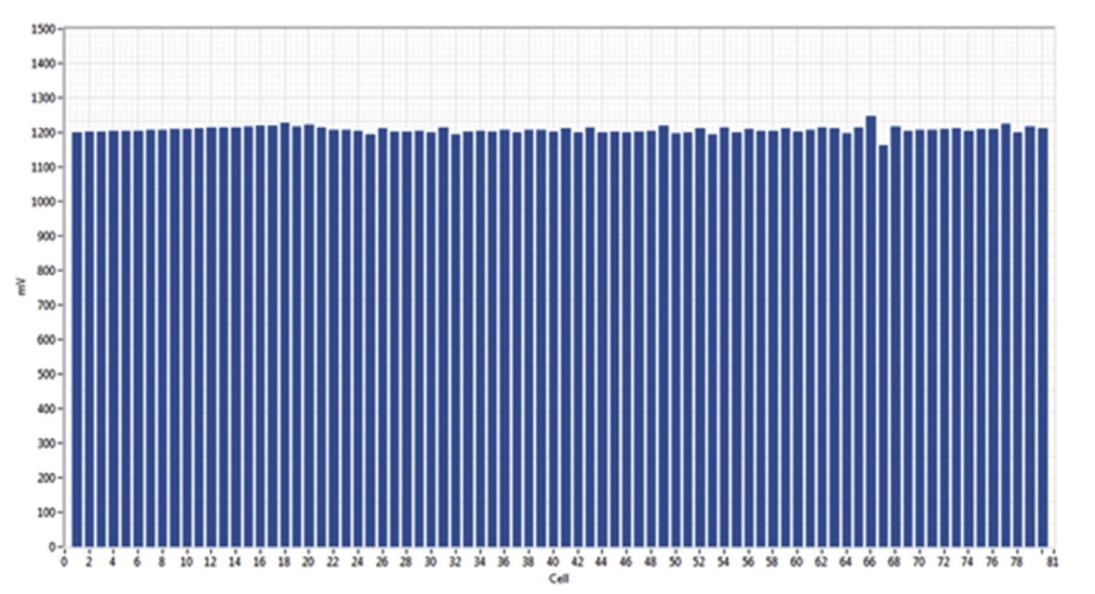
Figure 1: Example of a healthy stack with 80 cells (source: Vivas, F. J., et al.: Cell voltage monitoring All-in-One. A new low-cost solution to perform degradation analysis on air-cooled polymer electrolyte fuel cells.” International Journal of Hydrogen Energy 44.25 (2019): 12842-12856.)
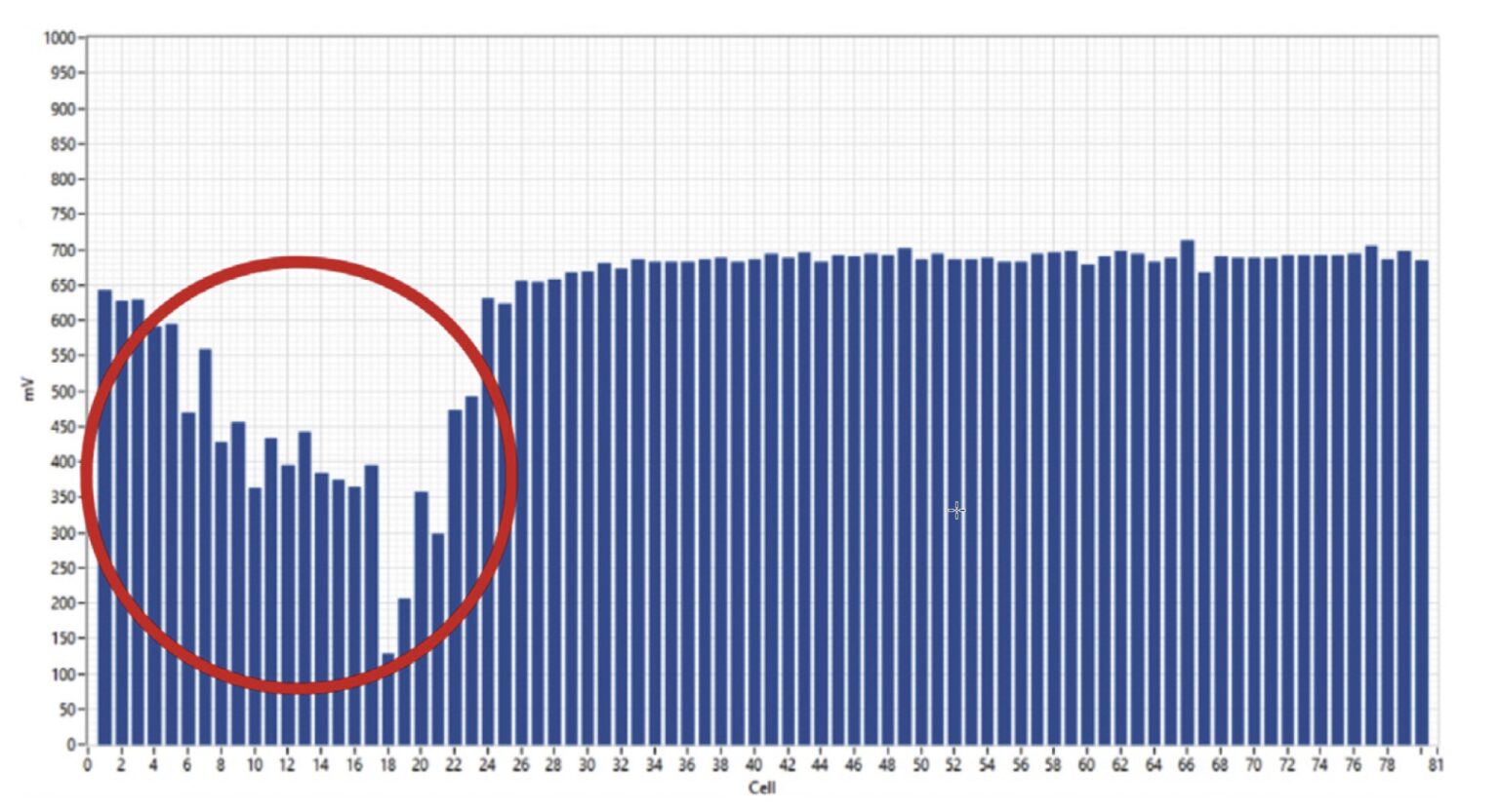
Figure 2: Example of a malfunctioning stack. Cell 6 to 24 show a significant voltage drop compared to the rest of the cells in the stack (source: Vivas, F. J., et al.: Cell voltage monitoring All-in-One. A new low-cost solution to perform degradation analysis on air-cooled polymer electrolyte fuel cells.” International Journal of Hydrogen Energy 44.25 (2019): 12842-12856.)
![]()
Which are the decisive parameters of a CVM system?
There are several important parameters of a cell voltage monitoring system to be considered. The cell voltages are measured differentially and thus the number of cells in the stack determines the required number of channels of the CVM system. For the fuel cell stack, the sufficient voltage measuring range of one channel is ±1.5 V. Modern CVM systems offering larger channel voltage range allow for monitoring groups of cells (useful for stacks with a large cell count, e.g., CVM-24P offers a range of ±5V). Furthermore, they can be used to monitor other electrical systems such as batteries or electrolysers as well.
The sampling rate of channels (usually expressed in samples per second or Hertz) is another critical specification, especially if the CVM system measures the cells sequentially. One should differentiate between the so-called internal sampling rate (higher and architecture-dependent value), and the all-channel sampling rate (a more practical value describing the measurement rate of the whole system). For real-time monitoring of the stack’s health, the sampling rate should be as high as possible to allow for a reliable detection of anomalies even in fast load transients (e.g., CVM-24P captures 500sps). To be able to transfer the acquired data to the stack’s control unit without further delays, a real-time communication interface such as a CAN bus is required.
The third decisive parameter of a CVM system is accuracy. Modern CVM systems offer 0.02 % of scale (again for example CVM-24P 0.02 % of range + 0.05 % of reading ). To reduce the amount of noise picked up along the cables, the CVM system should be positioned as close to the stack as possible, and the cable length should be minimised. Cables with shielding can further mitigate the noise.
Since the cell voltage is measured differentially, the individual channels can measure, depending on the stack size, up to hundreds of volts with respect to ground. To avoid damaging the CVM system, an insulation of the channels against high voltage is required.
Among other important criteria are daisy-chain support (to be able to measure hundreds of channels by connecting multiple CVM modules) as well as sufficiently high operating temperature resilience of the CVM system (to allow functioning as close to the running stack as possible). Furthermore, in transport applications, the CVM system together with the voltage tapping and cables need to be particularly resistant against vibration. Last but not least, the cost of the CVM system is also a decisive factor, especially for stack manufacturers producing stacks in high volumes.
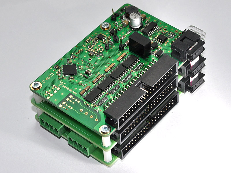
Example component cell voltage monitor
How many types of fuel cell voltage pick-up designs exist, and which is the best option?
Typically, the voltage of each cell of the stack is collected using a so-called CVM pick-up assembly. Interfacing of the fuel cell stack monitoring system with the individual cells (voltage tapping) can be done using simple connectors, spring connectors, spring wires or even soldered connections. The choice of the optimal connection is governed by limitations of stack design, in particular by cell pitch (i.e. distance between bipolar plates).
Automotive stacks are usually more compact and therefore offer only a narrow space for connection of the voltage tapping to the bipolar plates. Ideally, the voltage tapping should be planned during the stack design phase.

What kind of accessories are required for fuel cell stack monitoring equipment?
Depending on the application, the cell voltage monitoring system (CVM) can be connected either to a PC (typical for research applications) or a fuel cell stack control unit (e.g., real-time microcontrollers). Modern CVM systems can be equipped with a stack control unit allowing for a compact solution suitable especially for transport and portable applications.
Another required accessory is a software with GUI, providing real-time graphic representation of the cell voltages (research and development) as well as real-time diagnostics and control (field applications).
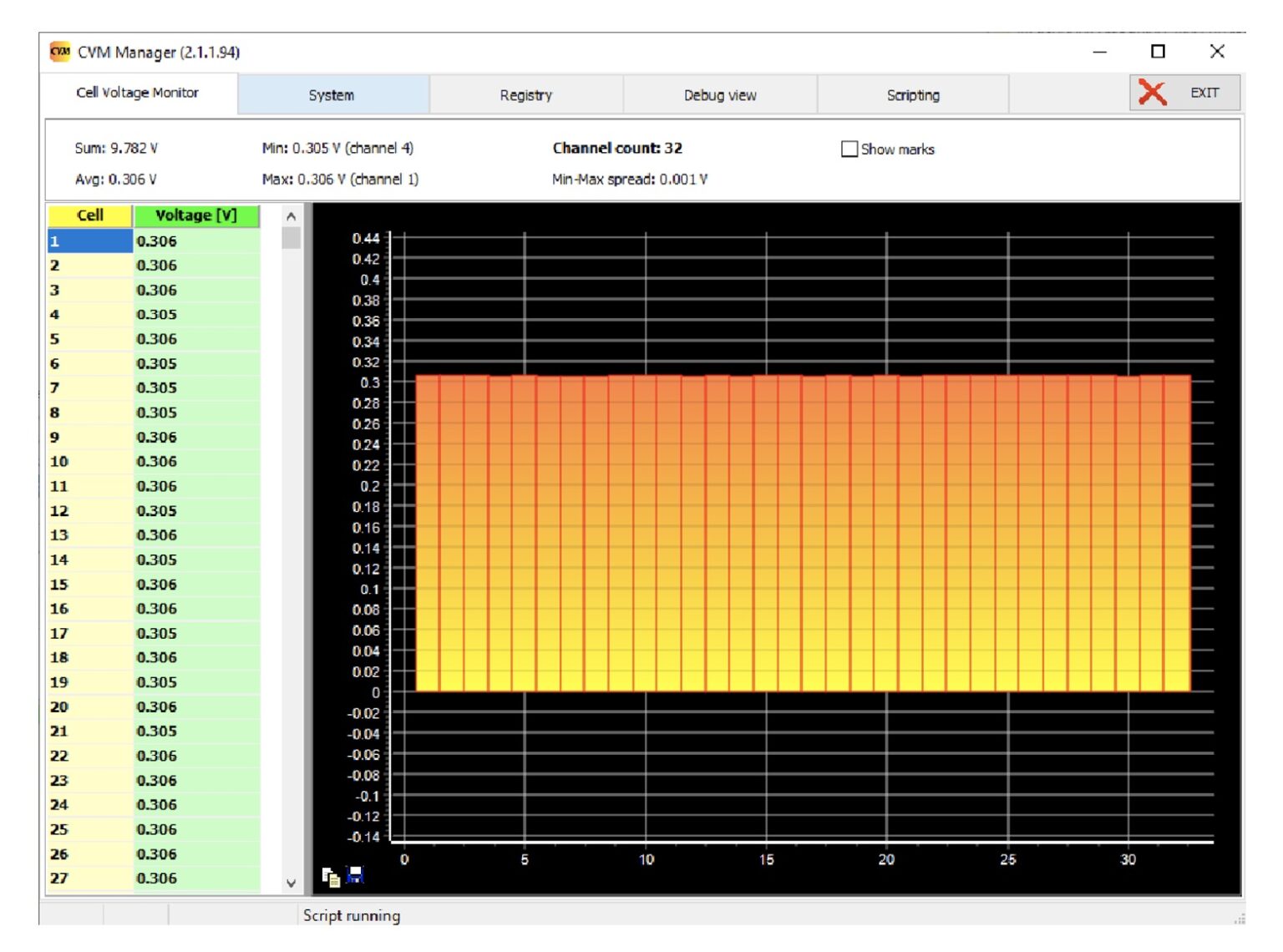
Figure 3: Example of a control software: CVM Manager (Cell Voltage Monitoring tab) from Kolibrik.net
Content contributed by Kolibrik.net
Kolibrik.net provides solutions and products mainly for H2FC technologies and electrochemistry. The electronics and software made by Kolibrik.net can cover many tasks ranging from basic and applied research, high-power cell and stack testing, stack control system prototyping to target application solutions. All products presented are on modular platform so they can be modified according to exact needs or parameters.
![]()
![]()


Last update: 15.1.2023