 Login
Login


Stöbern Sie auf unserem Marktplatz nach Wasserstoffventilen von führenden Anbietern!
Was ist ein Wasserstoffventil?
Wasserstoffventil sind kritische Sicherheitskomponenten, die in verschiedenen Wasserstoffanwendungen eingesetzt werden. Ein Wasserstoffventil steuert den Wasserstofffluss (flüssig/gasförmig) innerhalb des Systems und schaltet das System im Notfall oder bei Leckagen ab. Die Konstruktion von Wasserstoffventilen muss den extremen Betriebsbedingungen, wie hohem Druck, sehr niedrigen Temperaturen und manchmal übermäßigen Vibrationen, denen ein Wasserstoffventil ausgesetzt ist, Rechnung tragen. Dabei liegt der Schwerpunkt auf der Zuverlässigkeit und den Leistungskriterien der Ventile. Gleichzeitig müssen die Ventile während ihrer gesamten Lebensdauer den Sicherheitsanforderungen entsprechen.
Daher ist die Auswahl des richtigen Ventils je nach Anforderung und Anwendung entscheidend für einen sicheren und stabilen Betrieb aller Arten von Wasserstoffsystemen.


Welche Arten von Wasserstoffventilen gibt es?
Auf dem Markt gibt es verschiedene Arten von Wasserstoffventilen für unterschiedliche Anwendungen.
a) Wasserstoff Nadelventil
Wasserstoff Nadelventile werden verwendet, um den Durchfluss von Wasserstoff in gasförmiger oder flüssiger Form durch ein Gerät oder System zu regeln. Sie werden für eine genaue Durchflusskontrolle verwendet. Der Grund für die Bezeichnung Nadelventil liegt darin, dass das Ventil an einem Ende einen kleinen inneren Stößel enthält, der die Form einer Nadel hat. Dieser Teil befindet sich in der Maschine oder in der Rohrleitung und ist nicht sichtbar. Am anderen Ende des Stößels befindet sich ein Handgriff, das so genannte Handrad, mit dem sich das Ventil leicht und präzise drehen lässt.
Im geschlossenen Zustand passt der Kolben genau in den Sitz, der ein Teil des Geräts ist, das reguliert wird. Wird das Ventil jedoch gedreht, vergrößert sich der Spalt zwischen dem Kolben und dem Sitz. Dadurch kann die Substanz durch das Nadelventil fließen. Sie können das Nadelventil manuell oder automatisch mit Hilfe verschiedener Stellantriebe regulieren. Die Steuerung des Nadelventils durch ein automatisiertes Gerät unterstützt den optimalen Betrieb des Ventils für das System.
b) Wasserstoff Kugelhahn
Wasserstoff Kugelhähne sind in der Regel Absperrventile, die den Flüssigkeitsstrom durch das System mit Hilfe einer Drehkugel steuern. Die Drehkugel ist mit einem Loch oder einer Bohrung in der Mitte versehen, die den Durchfluss der Flüssigkeit entweder zulässt oder blockiert. Die Kugel ist an zwei Sitzen befestigt und hat eine Welle, die sie mit dem Steuermechanismus verbindet, der die Kugel dreht. So kann der Kugelhahn manuell oder automatisch gesteuert werden.
Im geöffneten Zustand befindet sich der mit der Kugel verbundene Steuerhebelarm parallel zum Rohr und die Flüssigkeit kann durch das System fließen. Wenn der Steuerhebelarm um eine Vierteldrehung (90 Grad) gedreht wird, wird er senkrecht zur Rohrleitung bewegt und das Ventil befindet sich im geschlossenen Zustand. Kugelhähne können mehrere Anschlüsse, d. h. Öffnungen im Ventil, haben. Dies hängt von der jeweiligen Anwendung ab.
c) Wasserstoff Rückschlagventil
Wasserstoff Rückschlagventile sind Einwegventile, die den Durchfluss der Flüssigkeit nur in eine Richtung zulassen und somit einen Rückfluss der Flüssigkeit im System verhindern. Damit sich das Rückschlagventil öffnet und den Durchfluss der Flüssigkeit zulässt, muss zwischen Ein- und Auslass ein Mindestdruck herrschen. Dieser Mindestvordruck wird als “Öffnungsdruck” des Rückschlagventils bezeichnet. Fällt der Vordruck unter den Öffnungsdruck oder entsteht ein Gegendruck, so schließt das Rückschlagventil.
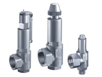
d) Wasserstoff Überdruckventil
Ein Wasserstoff Überdruckventil ist eine Sicherheitseinrichtung, die das System schützen soll, wenn der Druck im System über den angegebenen Auslegungsdruck oder den maximal zulässigen Betriebsdruck hinaus ansteigt. Wenn also der Druck im System über den eingestellten Druck steigt, wird das Ventil automatisch angehoben und gibt den Durchfluss des Mediums frei, wodurch der Druck abgebaut wird. Sobald der Druck im System unter den Wiedereinschaltdruck fällt, schließt sich das Ventil. Daher ist ein Überdruckventil wichtig, um Überdruckereignisse und Geräteausfälle zu verhindern.
e) Wasserstoff Durchflussregelventil
Wasserstoff Durchflussregelventile werden auch zur Steuerung des Flüssigkeitsstroms im System verwendet. Ein Wasserstoff Regelventil ähnelt in seiner Funktionsweise einem Nadelventil, d. h. es kann zur genauen Durchflussregelung eingesetzt werden. In geschlossenem Zustand verhindert es den Durchfluss, und wenn das Ventil allmählich geöffnet wird, nimmt auch der Durchfluss zu. Der Hauptunterschied zwischen einem Nadelventil und einem Durchflussregelventil besteht jedoch darin, dass bei einem Nadelventil der Durchfluss in beide Richtungen geregelt wird (bidirektional), während ein spezielles Durchflussregelventil den Durchfluss nur in eine Richtung regelt (und einen freien Durchfluss in die entgegengesetzte Richtung zulässt).
f) Wasserstoff Absperrventil
Ein Wasserstoff Absperrventil wird häufig als Wasserstoff-Magnetventil ausgeführt. Diese Art von Ventil wird verwendet, um den Durchfluss eines Mediums in einem System sicher zu stoppen oder fortzusetzen. Es besteht aus zwei Komponenten, dem Ventilkörper und dem Steuergerät. Das Steuerelement sorgt dafür, dass das Ventil wie gewünscht öffnet und schließt. Wenn alles richtig funktioniert, fließt das Medium reibungslos durch das Ventil. Tritt jedoch ein anormaler Zustand ein, wie z. B. eine übermäßige Flüssigkeitsausdehnung, schließt das Steuergerät den Durchflusskanal im Ventil. Er funktioniert also ähnlich wie ein elektrischer Schalter, der den Durchfluss entweder ganz stoppt oder ganz freigibt. Im Anwendungsfall als Wasserstoff Absperrventile können Absperrventile verwendet werden, um Abschnitte eines Wasserstoff-Kraftstoffkreislaufs zu isolieren.
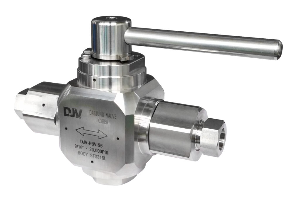
Beispiel: Wasserstoff-Kugelhahn
g) Kryogenische Wasserstoffventile
Kryogenische Wasserstoffventile werden meist in Bereichen mit sehr niedrigen Temperaturen eingesetzt, wo sie extrem kalten Temperaturen standhalten und effektiv arbeiten können. Er wird üblicherweise bei Temperaturen unter -150 °C zur Regulierung des Flüssigkeitsstroms eingesetzt. Kryo-Ventile werden normalerweise in einer geschlossenen Position gehalten, um kryogene Gase oder andere Medien sicher zu halten. Wenn der Druck steigt, wird das Tieftemperaturventil in eine offene Position geschoben, damit das Gas oder ein anderes Medium ungehindert durchfließen kann. Wenn der Druck wieder abfällt, schwenkt das Ventil zurück und ist mit einem speziellen Metallsitz blasendicht verschlossen, um ein Auslaufen zu verhindern.
Kryogenische Ventile bestehen in der Regel aus Materialien mit niedrigem Wärmeausdehnungskoeffizienten wie Edelstahl oder Messing, um zu verhindern, dass die Ventile bei niedrigen Temperaturen spröde werden und brechen. Konstruktionsmerkmale wie verlängerte Ventilhauben und Isolierung werden hinzugefügt, um die Wärmeübertragung zu minimieren und die Temperatur des Ventilkörpers und anderer Komponenten bei niedrigen Temperaturen zu halten.
h) Wasserstoff Durchgangsventile
Wasserstoff Durchgangsventile regeln den Flüssigkeitsstrom in einer Rohrleitung mit einem beweglichen Kegel/Scheibe-Element und einem feststehenden Ringsitz. Diese Ventile sind in der Regel in einem kugelförmigen Körper untergebracht, daher der Name “Durchgangsventil”. Es handelt sich nicht um ein bidirektionales Ventil. Das Geradsitzventil arbeitet mit einer Scheibe, die den Durchfluss einer Flüssigkeit in einer Rohrleitung drosselt, und besteht aus einem Sperrmaterial.
Durch Drehen des Handrads im Uhrzeigersinn bewegen sich Spindel und Ventilkegel nach unten, wodurch der Ventilkegel sicher zwischen den beiden Ventilsitzen positioniert wird, was zu einer vollständigen Abdichtung führt, die jegliches Austreten von Flüssigkeit verhindert. Umgekehrt bewirkt das Drehen des Handrads gegen den Uhrzeigersinn, dass sich die Spindel und der Ventilkegel nach oben bewegen, wodurch das Ventil aus seiner geschlossenen Position geöffnet wird und Flüssigkeit durch das Durchgangsventil fließen kann.
i) Wasserstoff Druckminderer
Wasserstoffdruckregler sind entscheidend für die Steuerung und Reduzierung des Drucks von Wasserstoffgas von einer Hochdruckquelle auf einen niedrigeren, besser kontrollierbaren Druck. Diese Druckminderer bestehen aus einer Einlassöffnung, einer Membran oder einem Kolbenmechanismus und einer Auslassöffnung. Wenn das Hochdruck-Wasserstoffgas in den Regler eintritt, wird der Innendruck überwacht. Übersteigt der Druck den gewünschten Sollwert, passt sich der Membran- oder Kolbenmechanismus an, um den Gasfluss zu drosseln und einen gleichmäßigen und kontrollierbaren Druck am Ausgang aufrechtzuerhalten. Dadurch kann der Regler den Gasfluss modulieren und den Druck auch bei Schwankungen des Eingangsdrucks im gewünschten Bereich halten. Somit tragen Wasserstoffdruckregler zum sicheren und zuverlässigen Betrieb von wasserstoffbasierten Systemen und Anwendungen bei.
j) Wasserstofftankventile
Wasserstofftankventile sind wichtige Komponenten zur Steuerung des Wasserstoffgasflusses in und aus Wasserstofftanks oder -flaschen. Sie bestehen aus verschiedenen Komponenten, darunter ein Ventilgehäuse, eine Spindel, ein Sitz und ein Antrieb, und können manuell oder automatisch betätigt werden.
Während des Befüllvorgangs ermöglicht das Ventil einen kontrollierten Durchfluss des Wasserstoffs von der Versorgungsquelle in den Tank, wodurch sichergestellt wird, dass der gewünschte Fülldruck erreicht wird. Beim Ablassen von Wasserstoff aus dem Tank erleichtert das Ventil die kontrollierte Freisetzung des Gases und leitet es an die vorgesehene Anwendung oder das nachgeschaltete System weiter. Sie verfügen auch über Funktionen wie Druckentlastungsvorrichtungen oder Berstscheiben, um Überdrucksituationen zu bewältigen. Diese Sicherheitsmechanismen tragen dazu bei, den Überdruck abzubauen, um potenzielle Gefahren zu vermeiden und die Integrität des Tanks zu erhalten.
Darüber hinaus berücksichtigen Wasserstofftankventile, die für die Speicherung von Wasserstoff bei niedrigen Temperaturen oder hohem Druck ausgelegt sind, die besonderen Eigenschaften und Anforderungen von Wasserstoffgas unter diesen Bedingungen. Sie können Temperatur-Druckentlastungsvorrichtungen (TPRDs) umfassen, die Gas bei bestimmten Temperaturschwellen sicher ablassen, sowie Überströmventile zur Begrenzung des maximalen Ausflusses im Falle eines Pipelinebruchs.
k) Kathoden Absperrventile
Kathodenisolierventile sind spezielle Ventile, die im Kathodenpfad eines Brennstoffzellensystems eingesetzt werden. Sie werden in der Regel in die Rohrleitungen oder Schläuche eingebaut, die den Kathodenraum eines Elektrolyseurs mit dem Elektrolytversorgungs- oder -umwälzsystem verbinden. Diese Ventile dienen zur Absperrung oder Steuerung des Elektrolytstroms im Kathodenraum eines Elektrolyseurs. Es sorgt für einen luftdichten Verschluss des Ein- und Ausgangs eines Brennstoffzellenstapels, wenn das System abgeschaltet ist. Dadurch werden konstante Bedingungen innerhalb des Brennstoffzellenstapels aufrechterhalten, was eine vorzeitige Alterung verhindert und einen schnellen Neustart des Systems ermöglicht. Kathoden-Isolierventen verfügen über ausfallsichere Funktionen, um den Brennstoffzellenstapel bei Bedarf sicher zu schließen. Außerdem ist ein elektrisches Stellglied zur präzisen Regelung des Massenstroms und des Drucks im Brennstoffzellenstapel integriert, was einen effizienten und sicheren Betrieb ermöglicht.
l) Wasserstoffdruck Magnetventil
Wasserstoffdruckmagnetventile sind elektromechanisch betriebene Geräte, die zur Steuerung des Wasserstoffgasflusses eingesetzt werden. Diese Ventile arbeiten mit einer Magnetspule, die ein Magnetfeld erzeugt, um einen Stößel im Inneren des Ventils zu bewegen und so das Ventil zu öffnen oder zu schließen. Sie sind für ihre kompakte Bauweise bekannt und werden häufig in Anwendungen eingesetzt, die eine präzise Steuerung des Flüssigkeitsdurchflusses erfordern. Wasserstoff-Druckmagnetventile bieten mehrere Vorteile, darunter schnelles und sicheres Schalten, geringer Energieverbrauch, hohe Zuverlässigkeit und Kompatibilität mit wasserstoffbasierten Anwendungen.
Es gibt zwei Haupttypen von Wasserstoff-Druckmagnetventilen: direkt wirkende und vorgesteuerte Ventile. Bei direktwirkenden Magnetventilen erzeugt die Magnetspule eine elektromagnetische Kraft, die einen Stößel direkt zum Öffnen oder Schließen des Ventils bewegt. Die Bewegung des Stößels basiert ausschließlich auf dem Magnetfeld. Bei vorgesteuerten Magnetventilen hingegen wird neben dem Magnetfeld ein Hilfssteuerventil verwendet. Wenn das Magnetventil aktiviert wird, öffnet sich das Vorsteuerventil und lässt eine kleine Menge Flüssigkeit in das Hauptventil einströmen. Diese Änderung des Systemdrucks öffnet dann das Hauptventil, um den Flüssigkeitsdurchfluss zu ermöglichen. Wenn die Magnetspule stromlos ist, schließt das Vorsteuerventil, wodurch das Hauptventil geschlossen und der Flüssigkeitsstrom gestoppt wird.
Was sind die wichtigsten Anwendungsfälle für die einzelnen Arten von Wasserstoffventil?
Flüssigwasserstoffventile werden in Wasserstofftankstellen, Druckflüssigkeitssystemen und Kompressionssystemen eingesetzt. In ähnlicher Weise wird ein Flüssigwasserstoffventil zur Durchflussregelung z. B. in Wasserstoff-Brennstoffzellen-Testsystemen, Wasserstofftankstellen, Speicher- und Produktionssystemen eingesetzt. Dies gilt insbesondere für Anwendungsfälle, in denen Wasserstoff in flüssiger Form nach Kompression oder kryogener Verflüssigung gehandhabt und verarbeitet wird.
Wasserstoffgasventile, wie sie in Elektrolyse- und Wasserstoffspeichersystemen zu finden sind, werden häufig als Kugelventile ausgeführt. Ein Wasserstoffgasventil kann als Absperrventil in Niederdruckanwendungen im Bereich der Wasserstoffspeicherung und -beförderung oder in Situationen, in denen mit einer Expansion des Wasserstoffs vom flüssigen in den gasförmigen Zustand gerechnet werden muss, eingesetzt werden.
Hochdruck-Wasserstoffventil werden als Überdruckventile eingesetzt, z.B. in Wasserstoffkesseln und -anlagen, an Druckbehältern, in der Verfahrenstechnik, bei der Speicherung und beim Transport von Wasserstoff. Ein Wasserstofftankventil wird normalerweise als Kugelabsperrventil ausgeführt. In der folgenden Tabelle sind die Anwendungsfälle für Wasserstoffventile aufgeführt:
| Typ des Ventils | Anwendungsfälle |
| Wasserstoff-Nadelventil | Wasserstofftankstellen, Druckflüssigkeitssysteme, Kompressionssysteme |
| Wasserstoff-Kugelhahn | Elektrolyse, Wasserstoffspeicherung |
| Wasserstoff-Rückschlagventil | Wasserstofftankstellen, Brennstoffzellen, Wasserstoffverarbeitung, Steuerung und Abschaltung von Prozesssystemen |
| Wasserstoff-Druckbegrenzungsventil Ventil | Wasserstoffkessel und -anlagen, Druckbehälter, Verfahrenstechnik, Speicherung und Transport von Wasserstoff |
| Wasserstoff-Durchflussregelventile | Wasserstoff-Brennstoffzellen-Testsysteme, Wasserstoff-Betankungs-, -Speicher- und -Herstellungssysteme |
| Wasserstoff-Absperrventile | Speicherung und Transport von Wasserstoff |
![]()
Was sind die wichtigsten Leistungskriterien der einzelnen Ventiltypen?
In der folgenden Tabelle sind die Spezifikationen für Wasserstoffventile aufgeführt, die je nach Art des Ventils als wichtige Leistungskriterien gelten:
| Typ des Ventils | Wichtige Leistungskriterien |
| Wasserstoff Nadelventil | Betriebsdruck, Anschluss- und Öffnungsgröße des Ventils, Flüssigkeitstemperatur und Ventilwerkstoff |
| Wasserstoff Kugelhahn | Dichtungsmaterial, Funktion des Kreislaufs, Betriebsdruck, Flüssigkeitstemperatur, Art des Ventilanschlusses und Ventilmaterial |
| Wasserstoff Rückschlagventil | Maximaler Flüssigkeitsdruck, Öffnungsdruck, Ventilwerkstoff, Fließverhalten |
| Wasserstoff Druckbegrenzungsventil | Einstelldruck, Gegendruck, Abblaseleistung, Ventil- und Dichtungsmaterial, Flüssigkeitstemperatur |
| Wasserstoff Durchflussregelventile | Betriebsdruck, Anschluss- und Öffnungsgröße des Ventils, Flüssigkeitstemperatur und Ventilwerkstoff |
| Wasserstoff Absperrventile | Betriebsdruck, Anschluss- und Öffnungsgröße des Ventils, Flüssigkeitstemperatur und Ventilwerkstoff |
Was ist die EC-79-Richtlinie für Wasserstoffventil?
Hersteller von Wasserstoffventil, die auf dem Markt konkurrieren, müssen die EG-79-Sicherheitsverordnung für wasserstoffbetriebene Fahrzeuge und Wasserstoffsysteme einhalten. Diese Richtlinie EG 79 gilt auch für Bauteile, die für diese Fahrzeugtypen entwickelt wurden. Sowohl flüssiger als auch komprimierter gasförmiger Wasserstoff fallen unter diese Verordnung.
Die EC79-Typgenehmigung gilt für alle Arten von Wasserstoffventilen und andere Bauteile. Lesen Sie den vollständigen Text der VERORDNUNG (EG) Nr. 79/2009 über die Typgenehmigung wasserstoffbetriebener Kraftfahrzeuge

EC-79 Anforderungen
- Wasserstoffkomponenten müssen elektrischen, mechanischen, thermischen und chemischen Betriebsbedingungen standhalten können, ohne undicht zu werden oder sich sichtbar zu verformen.
- Wasserstoffsysteme sollten vor Überdruck geschützt werden.
- Die für Wasserstoff führende Bauteile und Systeme, die in direktem Kontakt mit Wasserstoff stehen, verwendeten Werkstoffe müssen mit Wasserstoff verträglich sein.
- Wasserstoffkomponenten und -systeme sollten den zu erwartenden Temperaturen und Drücken während ihrer erwarteten Lebensdauer zuverlässig standhalten können.
- Bei Wasserstoff führenden Bauteilen mit gerichteter Strömung sollte die Strömungsrichtung deutlich angegeben werden.
- Wasserstoff führende Bauteile und Systeme sollten so konstruiert sein, dass sie installiert und vor Beschädigungen geschützt werden können.
Zu den Prüfungen, die an Wasserstoffventilen für die EC-79-Typgenehmigung durchgeführt werden, gehören Druckprüfung, Dichtheitsprüfung des Sitzes, Ozonalterungstest, Temperaturzyklustest, Wasserstoffverträglichkeitstest usw. für flüssigen Wasserstoff. Für gasförmigen Wasserstoff werden Tests wie Materialprüfungen, Korrosionsbeständigkeitsprüfungen, Dauertests usw. durchgeführt.
Letzte Aktualisierung: 01.02.2023